A solution for automotive gear shift switch based on Hangshun chip automotive grade MCU HK32A040C8T3
  Throughout the global development of passenger cars, automatic transmission has been widely adopted. Its simple and easy to learn, convenient and intelligent characteristics bring drivers a more comfortable driving experience, and also better adapt to urban traffic.  The implementation of the automatic shift function actually uses a gear shift switch instead of manual operation. The gear shift switch will control the shift fork and gear shift based on different engine speeds, vehicle speeds, and the driver's intention to press the accelerator. To achieve these automated operations, a shift switch requires a brain.  The Hangshun chip M0 series automotive grade MCU HK32A040C8T3 is such a "brain", applied in gear shift switch schemes. Its main function is to receive signals from the gear shift switch and convert these signals into electrical signals that can control the car's engine, transmission, and other parts, thereby simplifying driving operations and providing great convenience for the driver.  In the process of developing its new generation of electric vehicles, in order to ensure that the vehicle's performance, reliability, and safety reach the optimal level, after in-depth technical evaluation and multiple rounds of screening, Selis New Energy Vehicles finally chose a gear shift switch scheme based on the Hangshun chip HK32A040C8T3.  The Selis engineering team has conducted a rigorous review of the functional characteristics, processing speed, power consumption performance, environmental adaptability, and cost-effectiveness of the Hangshun HK32A040C8T3 MCU in multiple dimensions. Hangshun's MCU has successfully conquered the engineering team with its outstanding performance, especially in high reliability and strong anti-interference ability. In addition, HK32A040C8T3 has high integration and flexible peripheral interfaces, providing engineers with greater design freedom and optimization space, making the entire electronic control system more compact and efficient.  HK32A040 using ARM ® Cortex ®- M0 core, with a maximum operating frequency of 96MHz, built-in up to 124 Kbyte Flash and 10 Kbyte SRAM. By configuring the Flash controller registers, the remapping of interrupt vectors within the main Flash area can be achieved. And it supports traditional Flash Level 0/1/2 read-write protection and Flash code encryption (patented by Hangshun).  Strong scalability  32-bit ARM CPU architecture, good ecological environment  Rich peripheral resources to meet platform expansion  Multiple packaging options available for LQFP64, LQFP48, QFN32, and QFN28  high reliability  Car specification quality, compliant with AEC-Q100 Grade 1  Complies with ISO 9001 and IATFT 16949 quality management systems  Supports -40 ℃~125 ℃  High cost performance ratio  Equal performance/resources, with higher cost-effectiveness  Quality service  Complete ecological supporting facilities  15 years of design life, with a supply chain guarantee of over 15 years  The gear shift switch scheme based on the Hangshun Vehicle Class MCU HK32A040C8T3 has been successfully applied in the Sailis new energy vehicle, which not only improves the electronic control efficiency of the entire vehicle, but also achieves lower energy consumption and better user experience.  The Hangshun chip series vehicle grade MCU HK32A040 can be widely used in vehicle domain controllers, such as doors and windows, tail lights, wipers, anti-theft alarms, car keys, air conditioning, electric seats, etc.  Hangshun Chip adheres to the strategy of SoC+32-bit high-end MCU in automotive standards. In recent years, it has invested a large amount of research and development resources in the field of automotive electronics, committed to providing the market with higher reliability and more cost-effective automotive chip solutions, helping customers achieve a win-win situation in cost control and user experience.
Key word:
Release time:2024-05-09 11:48 reading:357 Continue reading>>
On the Fast Lane: NOVOSENSE's Ongoing Commitment to Automotive <span style='color:red'>Chip</span> Excellence
  Automobiles are undergoing increasing electrification and digitalization, from electric drive trains to immersive infotainment systems in the cockpit.  NOVOSENSE, a pioneering force in the automotive chips, recently unveiled several groundbreaking products aimed at enhancing performance, reliability, and efficiency in automotive applications.  NCA1462-Q1, an automotive-qualified CAN SIC based on innovative ringing suppression patent  NCA1462-Q1 is based on its proprietary innovative ringing suppression patent. Compared with CAN FD solution, NCA1462-Q1 is further compatible with the CiA 601-4 standard on the premise of meeting the ISO 11898-2:2016 standard, and can achieve a data rate of ≥8Mbps. With NOVOSENSE's patented ringing suppression function, NCA1462-Q1 maintains good signal quality even in the case of star network multi-node connection; in addition, its ultra-high EMC performance and more flexible VIO as low as 1.8V can effectively help engineers simplify system design and create high-quality automotive communication system.  NSHT30-Q1, a relative humidity (RH) and temperature sensor based on CMOS-MEMS  NSHT30-Q1 integrates a complete sensor system on a single chip, including a capacitive RH sensor, CMOS temperature sensor and signal processor, and an I2C digital communication interface. It is designed in DFN package with Wettable Flank, and the product size is 2.5mm×2.5mm×0.9mm. NSHT30-Q1's I2C interface features two selectable addresses with communication speed up to 1 MHz and supports a wide supply voltage range of 2.0V~5.5V.  NSOPA9xxx series, general-purpose operational amplifiers for automotive applications  NSOPA9xxx series is suitable for 40V high voltage and offers a variety of product models with bandwidth option of 1MHz/5MHz/10MHz and 1/2/4-channel. It meets the reliability requirements of AEC-Q100 Grade 1, and can operate from -40°C to 125°C. Different package versions are available to meet different customer needs: SOT23-5, SOP-8 for 1-channel; MSOP-8, SOP-8 for 2-channel; and TSSOP-14, SOP-14 for 4-channel.  NSD3604/8-Q1, a new automotive-qualified 4/8-channel multi-channel half-bridge driver  NSD3604/8-Q1 can drive multiple loads and is used in automotive domain control architecture. It covers 4/8-channel half-bridge drive which can drive 4 DC brushed motors, and achieve multi-channel high-current motor drive, and also be used as a multi-channel high-side switch drive. NSD3604/8-Q1 is suitable for multi-motor or multi-load applications, such as car window lifting, electric seats, door locks, electric tailgates, and proportional valves and other body control applications.
Key word:
Release time:2024-04-17 13:24 reading:428 Continue reading>>
<span style='color:red'>Chip</span>-on-Board (COB) vs. Package-on-Package (PoP)- Comparison and Applications
  The ever-evolving landscape of electronic devices demands innovation in packaging technologies. Among the array of approaches available, two prominent methods stand out: Chip-on-Board (COB) and Package-on-Package (PoP). These techniques play pivotal roles in the assembly, functionality, and miniaturization of electronic components, each with distinct advantages and applications.  Chip-on-Board (COB)  COB is a packaging technique that involves mounting bare semiconductor chips directly onto a substrate or a Printed Circuit Board (PCB). This method eliminates the use of individual packaging for each chip, opting instead for direct bonding or soldering onto the board’s surface. By doing so, COB reduces space requirements and enhances heat dissipation efficiency.  One of COB’s key strengths lies in its compactness. By eschewing traditional packaging, this approach significantly reduces the overall size of electronic devices, making it ideal for applications where space is a constraint. Moreover, the direct connection between the chip and the substrate minimizes signal interference, enhances electrical performance, and reduces circuit inductance and resistance.  COB technology finds widespread use across various industries. In automotive applications, COB is often utilized in LED lighting modules, offering higher brightness levels and superior thermal management due to the close arrangement of LED chips. Additionally, COB’s cost-effectiveness makes it appealing for applications where simplicity in circuitry is essential.  Package-on-Package (PoP)  In contrast to COB, Package-on-Package (PoP) involves vertically stacking multiple packaged chips within a single device. This configuration enables the integration of different functionalities or components, such as memory and processors, into a compact assembly. The stacking of chips facilitates enhanced performance without increasing the device’s footprint.  PoP’s primary advantage lies in its versatility. By vertically stacking chips, PoP allows for better integration of various components, leading to improved performance and reduced signal distortion due to shorter interconnection paths. This technology excels in accommodating diverse functionalities within limited space, making it a preferred choice for applications where performance and miniaturization are critical factors.  Mobile devices, particularly smartphones and tablets, heavily leverage PoP technology. These devices require high-performance capabilities within a confined space. PoP facilitates the integration of memory chips and processors, enabling seamless multitasking and high-speed data transfer without compromising on performance.  Chip-on-Board (COB) vs. Package-on-Package (PoP)- Comparison and ApplicationsWhen weighing the advantages of COB and PoP, the choice between the two largely depends on specific design requirements and application needs. COB’s strengths in compactness, cost-effectiveness, and thermal management make it suitable for applications where space optimization and simplicity in circuitry are crucial.  Conversely, PoP’s versatility in accommodating multiple functionalities within a confined space makes it ideal for devices requiring high performance without sacrificing miniaturization. Industries such as mobile technology heavily rely on PoP to enhance the capabilities of their devices while maintaining a compact form factor.  ConclusionBoth Chip-on-Board (COB) and Package-on-Package (PoP) are indispensable packaging technologies in the realm of modern electronics. Understanding their differences enables manufacturers and designers to make informed decisions based on specific requirements, contributing to the development of innovative and efficient electronic devices catering to diverse consumer needs.  By harnessing the capabilities of COB and PoP, the electronics industry continues to evolve, providing consumers with increasingly powerful yet compact devices across various applications, from consumer electronics to automotive and beyond.
Key word:
Release time:2024-03-21 16:32 reading:424 Continue reading>>
Vehicle-grade chips from Runic Technology
  We have recently released 11 Vehicle-grade chips that have passed AEC-Q100 Grade1&MSL 1 humidity level certification; The part number that have passed the vehicle specification certification this time include:  High-speed Comparator: LM2901XP-Q1; LM2903XK-Q1  General Operational Amplifier: RS8411XF-Q1; RS8414XQ-Q1  Analog Switch: RS2260XTSS16-Q1  Level Converter: RS0104XQ-Q1; RS0108XQ20-Q1  Logic Chip: RS1G125XC5-Q1;  Low Noise Operational Amplifier: RS622XTDE8-Q1  Parallel Voltage Reference Source: RS431AXSF3-Q1; RS432AXSF3-Q1  Vehicle-grade chips must have extremely low failure rates, high reliability, and normal operation at high and low temperatures, which requires high requirements for product design, development process, process design, process capability, and mass production control. All 11 Vehicle-grade chips released this time have passed the enhanced version of AEC-Q100 Grade 1 certification and humidity sensitivity level MSL 1 certification in authoritative third-party laboratories, with a theoretical design life of more than 25 years.  Currently, there are 38 Vehicle-grade chips from Runic Technology , and about 20 Vehicle-grade chips are still under certification; Runic's Vehicle-grade chips are widely applicable in various fields of automotive electronics, such as power domain, body domain, intelligent cockpit, etc. At the same time, they can be widely P2P compatible with equivalent signal chains, logic, analog switches, and other automotive grade chips from companies such as TI/ADI/Experia/Onsemi.
Key word:
Release time:2024-01-17 15:10 reading:1955 Continue reading>>
What types of chip packaging substrates are there?
  In the field of semiconductor packaging, many packaging types use packaging substrates, such as BGA (Ball Grid Array), PGA, QFP, CSP, SiP, PoP, etc. Different types of packaging use different packaging substrates. So what are the common packaging substrates? Keep reading!  What is the function of packaging substrate?  The packaging substrate has the following main functions in the package: electrical connection, mechanical support, heat dissipation, protection, etc.  What types of packaging substrates are there?  According to the material of the substrate, it is divided into rigid substrate and flexible substrate.  Rigid substrate refers to a substrate that has strong rigidity and cannot be bent. Flexible substrates refer to substrates that can be bent and folded. Rigid substrates have a fixed shape and form, while flexible substrates are thin and more flexible.  What type of material is the rigid substrate made of?  Common rigid substrate materials: FR4, BT, ABF, ceramic, etc.  FR4  FR4 is one of the most commonly used material types in printed circuit board (PCB) manufacturing. “FR4” stands for “Flame Retardant Type 4”. It is a composite material made of fiberglass cloth impregnated with epoxy resin, then hot pressed and cured. It has the characteristics of good flame retardancy, high mechanical strength, excellent electrical insulation performance and good thermal stability.  BT  BT material, which takes its name from its main chemical components: Bismaleimide and Triazine, is a more advanced and higher-performance epoxy resin substrate and has become the lamination of choice for many substrate manufacturers. BT material has a high glass transition temperature, usually higher than ordinary FR4 materials; low thermal expansion coefficient and dielectric constant; good insulation, etc. BT is the standard substrate material for BGA packages and can also be used for CSP packages.  ABF  ABF (Ajinomoto Build-up Film) is a highly rigid and highly durable material used in high-end chip packaging such as CPUs and GPUs. It was developed by Ajinomoto Company. It is a laminated film material and is usually used as an inner insulating material for packaging substrates.  Ceramics  Commonly used ceramic materials include aluminum oxide (Al2O3), aluminum nitride (AlN), beryllium oxide (BeO), silicon carbide (SiC), etc., which are relatively early laminated materials. Ceramic materials are first obtained in the form of powder through grinding to obtain particles of suitable particle size, and then are made through shaping, metallization, lamination, cutting, high-temperature sintering, grinding and polishing, nickel immersion, gold immersion, etc. They have a certain degree of brittleness and are suitable for high-frequency applications in chip products with high power and high reliability requirements.  What types of materials are used for flexible substrates?Common flexible substrate materials: PI (polyimide), PEEK (polyetheretherketone), PET (polyester), PDMS, etc.  What are the advantages and disadvantages of flexible substrates?  Advantages:  Flexibility and Conformity: Flexible substrates can conform to various shapes and surfaces, allowing them to be used in applications where rigid materials wouldn’t work. This flexibility enables innovative designs and applications in curved or irregular surfaces.  Lightweight and Thin: They are generally lighter and thinner than rigid substrates, which can be advantageous in applications where weight and thickness are critical factors, like portable devices or wearable technology.  Durability against Bending and Folding: Flexible substrates can withstand bending and folding, making them suitable for applications where frequent movement or deformation occurs without compromising their functionality.  Cost-Effectiveness: In some cases, flexible substrates can be more cost-effective than rigid alternatives, especially in large-scale manufacturing where materials and production processes might be less expensive.  Disadvantages:  Less Structural Support: Their flexibility can also be a disadvantage when structural support is necessary. This can limit their use in certain applications where a rigid base is needed for stability or mounting.  Limited Heat Resistance: Some flexible substrates might have lower heat resistance compared to rigid materials, which can be a drawback in applications where high temperatures are involved.  Reduced Electrical Performance: In certain electronic applications, flexible substrates may have limitations in terms of electrical performance, such as higher signal distortion or lower heat dissipation compared to rigid substrates.  Susceptibility to Damage: While flexible substrates are resilient to bending and folding, they might be more susceptible to damage from punctures, tears, or abrasions compared to rigid materials.  What are the advantages and disadvantages of rigid substrates?Advantages:  Stability and Durability: Rigid substrates are often more stable and durable compared to flexible ones. They maintain their shape and structural integrity well, making them suitable for various applications.  Support and Rigidity: They offer a stable surface for various processes like printing, painting, or mounting components. This stability can ensure precise and accurate outcomes in manufacturing.  Ease of Handling: Rigid substrates are often easier to handle during production processes, transportation, and installation due to their solid form.  Improved Performance: In some applications, such as electronic circuits, rigid substrates may offer better electrical performance due to reduced signal distortion and improved heat dissipation.  Disadvantages:  Limited Flexibility: The rigidity of these substrates can be a disadvantage when flexibility is required. They might not conform to curved surfaces or adapt well to uneven shapes, limiting their use in certain applications.  Susceptibility to Damage: Being rigid, they are more prone to cracking or breaking under stress or impact compared to flexible substrates. This makes them less suitable for applications where impact resistance is crucial.  Higher Cost: Rigid substrates can be more expensive than flexible alternatives due to the materials used and the manufacturing processes involved.  Transportation and Storage Concerns: Rigid substrates might require more careful handling during transportation and storage compared to flexible substrates, which can be rolled or folded.
Key word:
Release time:2024-01-04 13:53 reading:1216 Continue reading>>
3PEAK Launches TPU25401, a Highly Integrated Auto-Grade PMIC <span style='color:red'>Chip</span>
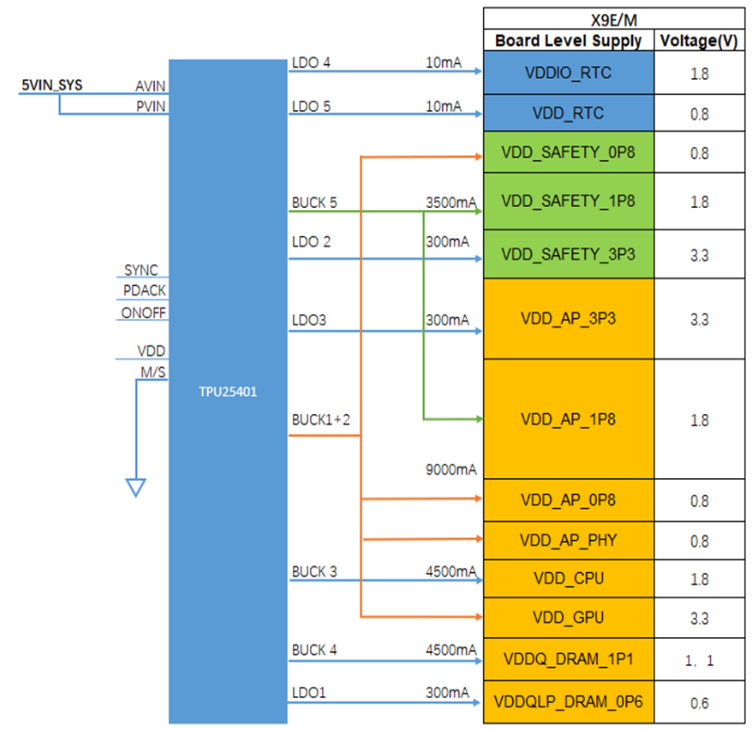
  With the rapid development of automotive technology, the electrification and intelligence of automobiles continue to advance, and intelligent cockpits and Advanced Driver Assistance Systems (ADAS) are becoming more prevalent. As a core component in automotive electronic systems, BMS devices directly impact the stability and efficiency of the entire system.  In response to these demands, 3PEAK has released TPU25401, a highly integrated auto-grade Power Management Integrated Circuit (PMIC). It is designed to power the main System-on-Chips (SoCs) in automotive intelligent cockpits, ADAS, and other systems, providing a new choice for power management in automotive electronic systems.TPU25401 adopts innovative technology and a compact design to meet the need for stable, efficient, and flexible power management in automotive intelligent cockpits, ADAS, and other systems. It introduces a breakthrough auto-grade power management solution for automotive electronics.  Typical Application Circuit of TPU25401  Key features of TPU25401 for application in automotive intelligent cockpits and ADAS systems include:  High Performance, High Integration  Includes 5 buck converters and 5 Low-Dropout Regulators (LDOs), with a total current output capacity exceeding 22 A.  Output voltage adjusted from 0.6 V to 3.7 V, with a 10 mV adjustment step.  Non-linear control internally, providing a fast dynamic load response speed, especially suitable for core digital chips such as SoCs.  6 × 6 mm 48-pin QFN package.  Flexible Configuration  Configurable default output voltage and power on/off sequence through One-Time Programmable (OTP) settings.  Programmable maximum output current capacity.  Dual-buck channel merging to meet the application requirements of a single high-current channel.  Master-slave architecture, allowing two PMICs to operate synchronously, providing more power rails with synchronous on/off sequences.  Safe and Reliable  Integrated with multiple protection mechanisms, including current limit protection, short-circuit protection, overload protection, and over-temperature protection. Automatic cut-off output in abnormal situations, protecting the automotive electronic system from damage and ensuring vehicle safety.  The flexible configuration of TPU25401 addresses the limitations of traditional PMICs that can only adapt to a single SoC platform. According to feedback from SoC partners and related Tier 1 feedback, TPU25401 can easily adapt to different SoCs in the automotive market. Taking the intelligent cockpit SoC X9M platform from SemiDrive as an example, only one TPU25401 is needed to meet all the power requirements of the system.  Minimum Functional Block Diagram of TPU25401 in Conjunction with SemiDrive's X9M Single-Chip Platform  Evaluation Board for TPU25401 in Conjunction with SemiDrive's X9M Single-Chip Platform  The TPU25401 BMS device for automotive intelligent cockpits, ADAS, and other systems offers a new solution.Through its highly integrated design, the TPU25401 ensures stable and efficient power for various hardware components in the complex automotive environment. Additionally, it responds rapidly to abnormal situations and provides automatic protection, significantly enhancing the system's safety and stability.TPU25401 includes features such as high integration, flexible configuration, and safety reliability, providing robust hardware support for the development of automotive electronics.
Key word:
Release time:2023-12-26 13:20 reading:1802 Continue reading>>
NVIDIA Confirms Development of “Compliance <span style='color:red'>Chip</span>s” for the Chinese Market
  According to IJIWEI’s report, NVIDIA recently confirmed that it is actively working on new “compliant chips” tailored for the Chinese market. However, these products are not expected to make a substantial contribution to fourth-quarter revenue.  On November 21, during NVIDIA’s earnings briefing for the third quarter of 2024, executives acknowledged the significant impact of tightened U.S. export controls on AI. They anticipated a significant decline in data center revenue from China and other affected countries/regions in the fourth quarter. The controls were noted to have a clear negative impact on NVIDIA’s business in China, and this effect is expected to persist in the long term.  NVIDIA’s Chief Financial Officer, Colette Kress, also noted that the company anticipates a significant decline in sales in China and the Middle East during the fourth quarter of the 2024 fiscal year. However, she expressed confidence that robust growth in other regions would be sufficient to offset this decline.  Kress mentioned that NVIDIA is collaborating with some customers in China and the Middle East to obtain U.S. government approval for selling high-performance products. Simultaneously, NVIDIA is attempting to develop new data center products that comply with U.S. government policies and do not require licenses. However, the impact of these products on fourth-quarter sales is not expected to materialize immediately.  Previous reports suggested that NVIDIA has developed the latest series of computational chips, including HGX H20, L20 PCIe, and L2 PCIe, specifically designed for the Chinese market. These chips are modified versions of H100, ensuring compliance with relevant U.S. regulations.  As of now, Chinese domestic manufacturers have not received samples of H20, and they may not be available until the end of this month or mid-next month at the earliest. IJIWEI’s report has indicated that insiders have revealed the possibility of further policy modifications by the U.S., a factor that NVIDIA is likely taking into consideration.
Key word:
Release time:2023-11-23 13:24 reading:1510 Continue reading>>
Microsoft Unveils In-House AI <span style='color:red'>Chip</span>, Poised for Competitive Edge with a Powerful Ecosystem
  Printed Circuit Boards (PCBs) are the fundamental building blocks of modern electronics, comprising a myriad of components meticulously arranged to enable the functionality of electronic devices. Identifying these components on a PCB and understanding their roles is essential for troubleshooting, repairs, and even designing electronic circuits.  In this comprehensive guide, we delve into the world of PCB components, unraveling their types, functionalities, and methods of identification.  Understanding PCB Components1. Resistors:  • Identification: Resistors are usually small, cylindrical components with colored bands indicating resistance values. Use a multimeter to measure resistance if the bands are unclear.  • Function: Resistors limit current flow in a circuit, adjusting voltage levels or protecting components.  2. Capacitors:  • Identification: Capacitors come in various shapes (cylindrical, rectangular) and sizes, often labeled with capacitance values and voltage ratings.  • Function: They store and release electrical energy, filtering signals or stabilizing voltage.  3. Diodes:  • Identification: Diodes appear as small cylindrical or square-shaped components with a stripe indicating polarity.  • Function: They allow current flow in one direction, blocking it in the opposite direction.  4. Transistors:  • Identification: Transistors come in different shapes (often three-legged), with part numbers indicating their type.  • Function: They amplify or switch electronic signals, serving as the basic building blocks of electronic devices.  5. Integrated Circuits (ICs):  • Identification: ICs are rectangular components with multiple pins. The part number often includes information about the manufacturer and type.  • Function: ICs integrate various functions (logic, memory, amplification) into a single package.  6. Inductors:  • Identification: Inductors resemble wire coils and are labeled with inductance values.  • Function: They store energy in a magnetic field and resist changes in current flow.  7. Connectors and Headers:  • Identification: Connectors are ports or slots for external connections. Headers are sets of pins for internal connections.  • Function: They facilitate the connection of external components or other PCBs.  Techniques for Identifying PCB componentsVisual Inspection:  Markings and Labels: Many components have printed markings indicating their values, part numbers, or manufacturers.  Physical Characteristics: Size, shape, and color often provide clues about a component’s type and function.  Multimeter and Testing:  Resistance Measurement: Use a multimeter in resistance mode to identify resistors and check for their values.  Capacitance Measurement: Multimeters with capacitance measuring capabilities can identify capacitors.  Datasheets and Component Manuals:  Online Resources: Manufacturers provide datasheets detailing component specifications and identification information.  Component Manuals: Some components have manuals with comprehensive details for identification.  Challenges and Conclusion  Identifying PCB components can present challenges due to the sheer diversity of shapes, sizes, and labeling conventions across manufacturers. Furthermore, miniaturization and surface-mount technology have made identification more intricate.  In conclusion, mastering the identification of PCB components is a foundational skill for electronics enthusiasts, engineers, and technicians. Utilizing a combination of visual inspection, testing tools, datasheets, and experience will empower individuals to decipher the complexities of PCBs, enabling effective troubleshooting, circuit design, and maintenance within the dynamic landscape of electronics.
Key word:
Release time:2023-11-23 13:19 reading:1620 Continue reading>>
What is a memory chip?  What are the types of memory chips?
  Memory chips are the main components used for storage In the realm of computing and digital devices, and play a very important role in the entire integrated circuit market.  These chips serve as the foundation upon which our digital world operates, facilitating the storage and retrieval of information in devices ranging from smartphones and laptops to complex servers and embedded systems.  What is a memory chip?A memory chip, fundamentally an integrated circuit (IC), is a crucial electronic component designed to store, retrieve, and manage data within a digital device. These chips come in various types and configurations, each tailored to serve specific purposes within electronic systems.  What are the types of memory chips?RAM (Random Access Memory): One of the most common types of memory chips, RAM is volatile memory used by computers to temporarily store data that the CPU needs quick access to during operation. It enables swift read and write operations, facilitating multitasking and overall system performance.  ROM (Read-Only Memory): Unlike RAM, ROM is non-volatile memory, meaning it retains data even when the power is turned off. ROM is commonly used to store firmware and permanent instructions essential for booting up devices and initializing hardware components.  Flash Memory: This non-volatile memory type finds its application in devices like USB drives, Solid State Drives (SSDs), memory cards, and embedded systems. Flash memory allows for both reading and writing operations, making it suitable for storing files, applications, and operating systems.  EEPROM (Electrically Erasable Programmable Read-Only Memory): EEPROM combines the qualities of both volatile and non-volatile memory. It’s rewritable and often used in smaller capacities to store configuration settings and small amounts of essential data.  What are the applications of memory chips?The ubiquity of memory chips spans across an extensive array of applications and devices, playing a pivotal role in their functionality:  • Computers and Laptops: RAM enables quick access to data during computations, while ROM stores firmware and BIOS instructions essential for system startup.  • Smartphones and Tablets: Memory chips in these devices handle data storage for applications, media files, and the operating system, ensuring smooth multitasking and user experience.  • Digital Cameras and Camcorders: These devices utilize memory chips to store photos, videos, and settings, allowing users to capture and retain precious moments.  • Embedded Systems and IoT Devices: Memory chips facilitate the functioning of embedded systems and IoT devices, managing data crucial for their operations in various industries like healthcare, automotive, and home automation.  How to make a computer chip?The creation of a memory chip involves intricate processes conducted in specialized semiconductor fabrication plants. The process can be summarized in several key steps:  Design and Layout: Engineers meticulously design the chip’s layout, determining the arrangement and connections of transistors and circuits.  Lithography: A crucial step where the chip’s design is imprinted onto a silicon wafer using photolithography techniques.  Etching and Doping: Unwanted portions of the silicon wafer are removed, and specific regions are doped with materials to alter their conductivity and create the desired electronic components.  Layering: Multiple layers of conductive and insulating materials are deposited onto the wafer to form intricate circuitry.  Testing and Packaging: The fabricated chips undergo rigorous testing to ensure functionality and quality. Once validated, they are packaged into final products for integration into various devices.  What is the difference between a logic chip and memory chip?While both logic and memory chips are essential components of electronic systems, they serve distinct functions:  Logic Chip:  A logic chip is designed to perform computational tasks, execute instructions, and manage the flow of data within a digital device. These chips contain integrated circuits that implement logical operations, arithmetic calculations, and control functions. They are the brains of a system, carrying out operations based on instructions received from software or firmware.  Examples of logic chips include Central Processing Units (CPUs), Graphics Processing Units (GPUs), microcontrollers, and Application-Specific Integrated Circuits (ASICs). CPUs, for instance, process data, perform calculations, and execute instructions, while GPUs specialize in handling graphics-related tasks.  Memory Chip:  In contrast, a memory chip is specifically dedicated to storing and retrieving data. These chips don’t perform computational or logical operations but instead focus on holding information temporarily or permanently within a system. Memory chips are responsible for enabling the storage and retrieval of data for various purposes, such as program execution, data manipulation, or long-term storage.  Types of memory chips include Random Access Memory (RAM), Read-Only Memory (ROM), Flash Memory, and Electrically Erasable Programmable Read-Only Memory (EEPROM). RAM, for example, stores data temporarily while the system is running, allowing quick access for the CPU to carry out operations. ROM holds essential instructions and data that remain intact even when the power is turned off. Flash memory is used for non-volatile storage in devices like USB drives and SSDs, while EEPROM allows for rewritable non-volatile storage in smaller capacities.  How long does a memory chip last?  The longevity of memory chips varies based on usage, quality, and environmental factors. Under normal operating conditions, these chips can last for many years, potentially even decades. However, excessive usage, high temperatures, or voltage fluctuations may impact their lifespan.
Key word:
Release time:2023-11-20 14:33 reading:1232 Continue reading>>
Microsoft First In-House AI <span style='color:red'>Chip</span> “Maia” Produced by TSMC’s 5nm
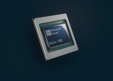
  On the 15th, Microsoft introducing its first in-house AI chip, “Maia.” This move signifies the entry of the world’s second-largest cloud service provider (CSP) into the domain of self-developed AI chips. Concurrently, Microsoft introduced the cloud computing processor “Cobalt,” set to be deployed alongside Maia in selected Microsoft data centers early next year. Both cutting-edge chips are produced using TSMC’s advanced 5nm process, as reported by UDN News.  Amidst the global AI fervor, the trend of CSPs developing their own AI chips has gained momentum. Key players like Amazon, Google, and Meta have already ventured into this territory. Microsoft, positioned as the second-largest CSP globally, joined the league on the 15th, unveiling its inaugural self-developed AI chip, Maia, at the annual Ignite developer conference.  These AI chips developed by CSPs are not intended for external sale; rather, they are exclusively reserved for in-house use. However, given the commanding presence of the top four CSPs in the global market, a significant business opportunity unfolds. Market analysts anticipate that, with the exception of Google—aligned with Samsung for chip production—other major CSPs will likely turn to TSMC for the production of their AI self-developed chips.  TSMC maintains its consistent policy of not commenting on specific customer products and order details.  TSMC’s recent earnings call disclosed that 5nm process shipments constituted 37% of Q3 shipments this year, making the most substantial contribution. Having first 5nm plant mass production in 2020, TSMC has introduced various technologies such as N4, N4P, N4X, and N5A in recent years, continually reinforcing its 5nm family capabilities.  Maia is tailored for processing extensive language models. According to Microsoft, it initially serves the company’s services such as $30 per month AI assistant, “Copilot,” which offers Azure cloud customers a customizable alternative to Nvidia chips.  Borkar, Corporate VP, Azure Hardware Systems & Infrastructure at Microsoft, revealed that Microsoft has been testing the Maia chip in Bing search engine and Office AI products. Notably, Microsoft has been relying on Nvidia chips for training GPT models in collaboration with OpenAI, and Maia is currently undergoing testing.  Gulia, Executive VP of Microsoft Cloud and AI Group, emphasized that starting next year, Microsoft customers using Bing, Microsoft 365, and Azure OpenAI services will witness the performance capabilities of Maia.  While actively advancing its in-house AI chip development, Microsoft underscores its commitment to offering cloud services to Azure customers utilizing the latest flagship chips from Nvidia and AMD, sustaining existing collaborations.  Regarding the cloud computing processor Cobalt, adopting the Arm architecture with 128 core chip, it boasts capabilities comparable to Intel and AMD. Developed with chip designs from devices like smartphones for enhanced energy efficiency, Cobalt aims to challenge major cloud competitors, including Amazon.
Key word:
Release time:2023-11-17 16:00 reading:1513 Continue reading>>

Turn to

/ 21

  • Week of hot material
  • Material in short supply seckilling
model brand Quote
TL431ACLPR Texas Instruments
RB751G-40T2R ROHM Semiconductor
CDZVT2R20B ROHM Semiconductor
MC33074DR2G onsemi
BD71847AMWV-E2 ROHM Semiconductor
model brand To snap up
ESR03EZPJ151 ROHM Semiconductor
TPS63050YFFR Texas Instruments
STM32F429IGT6 STMicroelectronics
BP3621 ROHM Semiconductor
IPZ40N04S5L4R8ATMA1 Infineon Technologies
BU33JA2MNVX-CTL ROHM Semiconductor
Hot labels
ROHM
IC
Averlogic
Intel
Samsung
IoT
AI
Sensor
Chip
About us

Qr code of ameya360 official account

Identify TWO-DIMENSIONAL code, you can pay attention to

AMEYA360 mall (www.ameya360.com) was launched in 2011. Now there are more than 3,500 high-quality suppliers, including 6 million product model data, and more than 1 million component stocks for purchase. Products cover MCU+ memory + power chip +IGBT+MOS tube + op amp + RF Bluetooth + sensor + resistor capacitance inductor + connector and other fields. main business of platform covers spot sales of electronic components, BOM distribution and product supporting materials, providing one-stop purchasing and sales services for our customers.