- Ameya360 Component Supply Platform >
- Trade news >
- What is an inductor ?
What is an inductor ?
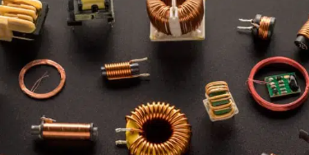
An inductor is a passive electronic component designed to store energy in the form of a magnetic field. It’s typically made of a coil of wire wound around a core material, such as iron or ferrite. When an electric current flows through the coil, it generates a magnetic field around it. The strength of this magnetic field is directly proportional to the current flowing through the coil.

One of the fundamental properties of an inductor is its ability to resist changes in the current flowing through it. This property is known as inductance, denoted by the symbol “L,” and it’s measured in henries (H). Inductors are widely used in electronic circuits for various purposes, including filtering, energy storage, and signal processing. They’re often employed in conjunction with capacitors to create filters that block certain frequencies or pass others, forming essential components of many electronic devices and systems.
What does an inductor do?
Inductors play various important roles in circuits, and here are their main functions:
1. AC Blocking/DC Passing: In a DC circuit, an inductor almost doesn’t impede the flow of current, acting like a short circuit, i.e., “passes DC.” However, in an AC circuit, an inductor generates reactance (XL = 2πfL), which impedes the flow of AC, increasing with frequency, i.e., “blocks AC.”
2. Filtering: Inductors combined with capacitors can form various filters, such as low-pass filters, high-pass filters, etc., used to remove noise or specific frequency components from circuits, making the output signal purer.
3. Oscillation: Combined with capacitors, they form LC oscillating circuits. When the circuit’s natural frequency matches the external signal frequency, oscillation can occur, used in signal generation and amplification circuits.
4. Tuning and Selectivity: In wireless radio and communication systems, combinations of inductors and capacitors can be used for selectivity, allowing signals of specific frequencies to pass while suppressing others, such as selecting different broadcast channels on a radio.
5. Energy Storage: Inductors can store magnetic field energy. In circuits like switch-mode power supplies, inductors can store energy when the switch is on and release it when the switch is off, achieving voltage conversion and current smoothing.
6. Delay and Band-Rejection: Inductors can introduce phase delay in signals, used in time-delay circuits or to filter out signals of specific frequencies (band-rejection).
7. Choking: In power supply circuits, inductors act as choke coils, capable of preventing high-frequency noise from entering sensitive circuits or stopping ripple currents in DC circuits, forming filter circuits with capacitors to provide smoother DC output.
8. Signal Selection and Separation: Common-mode inductors and differential-mode inductors are used respectively to filter out common-mode noise and differential-mode noise, enhancing signal purity.
9. Impedance Matching: In circuits where different impedance matching is needed between circuit sections, inductors can be used to adjust impedance to optimize signal transmission efficiency.
How to choose an inductor?When selecting an inductor, several key factors need to be considered:
1. Rated Current: The rated current of an inductor refers to the maximum current that can continuously pass through the inductor without causing it to overheat. When selecting an inductor, ensure that the chosen inductor’s rated current is greater than or equal to the maximum operating current in the circuit.
2. Inductance Value: The inductance value (L, typically measured in henries [H], millihenries [mH], or microhenries [μH]) is determined based on the specific requirements of the circuit. For example, in filter circuits, the inductance value affects the frequency characteristics of the filter; in oscillating circuits, it relates to the oscillation frequency. Choosing the correct inductance value is crucial for the circuit’s functionality.
3. Self-Resonant Frequency: For high-frequency applications such as RF filters, the self-resonant frequency (SRF) of the inductor is an important parameter. Ensure that the operating frequency of the selected inductor is lower than its self-resonant frequency to avoid performance degradation or instability.
4. DCR (DC Resistance): DC resistance affects the efficiency and heating of the inductor, especially in high-current applications. Lower DCR can reduce energy losses but typically implies increased cost.
5. Package Size and Form: In practical applications, space constraints are also important. Choose appropriate package sizes and shapes (such as vertical, horizontal, shielded, or unshielded) to meet PCB layout requirements.
6. Cost: Different types of inductors (such as iron core, air core, ferrite core, etc.) and manufacturing processes affect cost. Choose inductors that offer high cost-effectiveness while meeting performance requirements.
7. Operating Temperature Range: Ensure that the inductor’s operating temperature range covers the requirements of the application environment, especially in high-temperature or highly variable temperature environments.
8. Stability: For applications requiring high stability (such as precision measuring instruments), select inductors with low temperature coefficients and low aging rates.
Inductor selection is a comprehensive process that requires consideration of specific application scenarios, circuit design requirements, and cost budgets. In the initial design phase, it may also be necessary to use simulation software to verify the impact of inductor parameters on circuit performance.
What are the types of inductors?
The classification of inductors is diverse, and they can be categorized into multiple types based on different criteria. Here are some primary classification methods for inductors:
1. Based on the magnetic core properties:
– Air-core coils: Without a magnetic core, suitable for high-frequency applications.
– Ferrite-core coils: Use ferrite as the magnetic core, suitable for medium to high-frequency applications.
– Iron-core coils: Use iron material as the magnetic core, suitable for low-frequency and power applications.
– Copper-core coils: Less common, used for special occasions.
2. Based on the winding structure:
– Single-layer flat-wound air-core inductor coils
– Layer-wound air-core inductor coils
– Multi-layer air-core inductor coils
– Toroidal inductor coils
– Wire wound type: Traditional construction, where the coil is wound around the magnetic core.
– Stacked type: Made by stacking multiple layers of metal sheets, suitable for surface mounting.
– Braided type and thin-film inductors: Suitable for specific high-frequency or miniaturization requirements.
3. Based on the operating frequency:
– High-frequency inductors: Used for radio frequency and high-frequency signal processing.
– Intermediate-frequency inductors: Applied in circuits with a moderate frequency range.
– Low-frequency inductors: Suitable for power filtering and low-frequency signal processing.
4. Based on structural characteristics:
– Magnetic-core coils
– Variable inductors: Inductance value can be adjusted as required.
– Color code inductors: Inductance value identified through color codes.
– Coreless coils: Suitable for high-frequency applications.
5. Based on installation form:
– Vertical inductors, horizontal inductors, through-hole inductors, surface mount inductors, etc., adaptable to different PCB designs.
6. Based on usage:
– Oscillating inductors, tuning inductors, deflection yoke coils, choke coils, filter inductors, isolation inductors, compensation inductors, etc.
7. Based on packaging form:
– Standard inductors, toroidal inductors, epoxy resin inductors, surface mount inductors, etc.
8. Based on whether inductance is adjustable:
– Fixed inductors: Inductance value cannot be changed after manufacturing.
– Adjustable inductors: Inductance value can be changed through mechanical adjustment.
9. Based on coupling methods:
– Self-induction coils: Current variation induces voltage within itself.
– Mutual-induction coils (transformers): Current variation in one coil causes voltage or current variation in another coil.
How to identify inductor?There are several common methods for identifying inductors, and below are some of the main ones:
1. Direct Marking Method:
This is the most straightforward identification method, directly labeling the nominal inductance of the inductor using numbers and alphanumeric symbols on the body of the inductor. For example, “10μH” may be directly written to indicate an inductance of 10 microhenries, with the letter following the unit possibly indicating the tolerance range.
2. Alphanumeric Method:
Using a combination of numbers and specific alphanumeric symbols to identify the inductance value and its tolerance. For example, “1R5” might represent an inductance of 1.5μH, where “R” indicates the decimal point position, and the unit is typically nH or μH.
3. Color Ring Marking Method:
Similar to the color ring identification of resistors, inductors can also be represented using color rings to indicate information such as inductance value and tolerance grade. Generally, the rings are counted from one end, and the inductance value is calculated based on the color code for the value and multiplier, with the last ring representing the tolerance.
4. Surface Mount Inductor Identification:
For surface mount inductors, their identification may include size codes (such as 3020 indicating 3.0mm x 2.0mm) and the inductance value directly printed on the component (such as 100, 220, etc.). These identifications typically appear in numeric form and may not include detailed tolerance information due to the small size.
5. Other Identifications:
In addition to the above methods, some inductors may also be identified using specific part numbers or coding systems, which require consulting the manufacturer’s datasheets to decode.
Understanding the methods of identifying inductors is crucial for correctly recognizing and using inductor components, especially in the design, maintenance, and troubleshooting processes of electronic circuits.
ConclusionInductors are indispensable components in electronic circuits, playing vital roles in a wide range of applications. From filtering out noise to energy storage and signal processing, inductors serve diverse functions that contribute to the functionality and efficiency of electronic devices and systems.
Understanding the characteristics and classifications of inductors is crucial for selecting the right component for specific circuit requirements. Moreover, the identification methods of inductors, such as direct marking, alphanumeric codes, or color ring markings, provide essential information for circuit design, maintenance, and troubleshooting.
Online messageinquiry
- Week of hot material
- Material in short supply seckilling
| model | brand | Quote |
|---|---|---|
| RB751G-40T2R | ROHM Semiconductor | |
| MC33074DR2G | onsemi | |
| TL431ACLPR | Texas Instruments | |
| BD71847AMWV-E2 | ROHM Semiconductor | |
| CDZVT2R20B | ROHM Semiconductor |
| model | brand | To snap up |
|---|---|---|
| ESR03EZPJ151 | ROHM Semiconductor | |
| STM32F429IGT6 | STMicroelectronics | |
| TPS63050YFFR | Texas Instruments | |
| BP3621 | ROHM Semiconductor | |
| BU33JA2MNVX-CTL | ROHM Semiconductor | |
| IPZ40N04S5L4R8ATMA1 | Infineon Technologies |
- Week of ranking
- Month ranking
Qr code of ameya360 official account
Identify TWO-DIMENSIONAL code, you can pay attention to


Please enter the verification code in the image below:


